

Recently, a friend of mine wanted to upgrade the quasi-escape-room at the bottom of his garden by adding sound and lights to it.
The key idea of the room is that the punter enters a secret code on 6 toggle switches. If the code is right a treasure chest opens. I wanted to add some theatrical sounds and lights before the chest was opened.
These are brief notes on the project. Although it worked, if I were starting afresh now, I’d tackle things rather differently. Accordingly I’m not publishing the design files and software, though if you’re interested, please do contact me.
Broad design
It wasn’t entirely clear to me what would be needed so I thought it prudent to design a kit of parts which could be deployed as needed. That led to three boards:
A brain board1 based around a Raspberry Pi Pico. This also ended up containing miscellaneous circuitry.
An output board2 which provides a bunch of 12V outputs with PWM drive. These were used to drive the panel indicators and analogue meters.
A front panel3 with battery connectors and toggle switches.
To connect these boards I thought I2C would be suitable, particularly if it were made more robust by converting it to a differential signal with NXP’s PCA96154 chip. These chips also handled converting the 5V I2C signals to 3.3V logic for e.g. the Pico.
I used RJ-45 ethernet cables to carry power and the differential signals. This approach is similar to Sparkfun’s design5.
What failed
PCA9615
At first I had real trouble getting the PCA9615s to work reliably: they would randomly fail permanently, and once failed got very hot. I found similar stories on the NXP forum: 16, 27.
Somewhat inspired by those stories, I added diodes to make sure that the voltages of Vcc, the differential lines and ground had the right order. After this, the problems went away.

What worked well
Micropython
Writing the controller code in Micropython worked well. It was easy to find example code on the web for all of the devices, and the code ran quickly enough without any optimization.
Besides being quick to write, it meant that anyone could modify the code in future without having to learn C or install a toolchain.
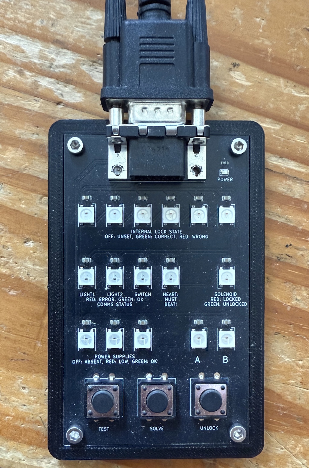
Status Panel
Although not a necessary part of the project I added a removable status display (much like the original sense of Blinkenlight) which was just a string of WS2812 Neopixels driven by the Pico, plus a few buttons for simple control.
An old-fashioned 9-way D-connector made it easy to connect the panel as needed, and suitable cables are easy to acquire, cheap, and reliable.
The board was fabricated at JLCPCB, and then attached to a thin 3D-printed case. Again, all easy and cheap, yet it looked great.
Hard constraints in hardware
One of the few hard contraints in the project is that the solenoid which open the treasure chest should only be powered for a brief time (~25ms).
Rather than rely on the microcontroller to turn this off in a timely fashion I implemented a simple monostable with discrete components: no matter what havoc the solenoid wrought to the power-rails I was confident that it wouldn’t last long.

Were I starting now
Hindsight, they say, is always 20/20 vision. Were I starting now I’d change the design considerably.
WS2811
I had forgotten that you could buy the controller part of a NeoPixel as a separate chip, the WS28118. If I were starting again now, I would use these to control the panel indicators and meters.
This would be simpler: the design would have a single central box with almost everything else being a 12V Neopixel string.
Avoiding differential I2C
Having offloaded all the blinkenlights to various sorts of Neopixel, I’d be pretty tempted to put everything else on a single board. Even if the keyboard still used I2C devices, it would be close enough to the microcontroller that no special precautions need be taken.
Better sound control
Besides the blinkenlights, there’s sound provided by a DFRobot DFPlayer9 MP3 player which is controlled by a serial UART on the Pico. It works well, but there seems to be a bit of latency when responding to commands and it’s hard to know exactly when a track finishes playing. Accordingly it’s hard to synchronize sound and lights. Were I starting now, I’d explore using streaming the audio data straight from the Pico over I2S.
Conclusion
A fun project, which worked, but if I started again I’d do it differently. A learning experience in other words!
References
- 1. brain-sch.svg
- 2. light-sch.svg
- 3. switch-sch.svg
- 4. https://www.nxp.com/docs/en/data-sheet/PCA9615.pdf
- 5. https://learn.sparkfun.com/tutorials/qwiic-differential-i2c-bus-extender-pca9615-hookup-guide/all
- 6. https://community.nxp.com/t5/Other-NXP-Products/PCA9615-Failures/td-p/1302064?profile.language=en
- 7. https://community.nxp.com/t5/Other-NXP-Products/PCA9615-fails-after-short-time/td-p/1810326
- 8. https://www.tme.eu/Document/26d574b43ad9ddaffa4d5bcd140ec145/WS2811.pdf
- 9. https://www.dfrobot.com/product-1121.html
![[ Atom Feed ]](../../atom.png "Atom Feed")