

Update June 2018: Although I continue to use the hardware described below, I have completely replaced the software with a stack targetting Apple’s HomeKit API. You can read about that in another article1.
 2
2
Introduction
For a while I’ve wanted a lamp on my desk which throws a reasonable amount of light around, and I took the opportunity to scratch a few ‘I want to play with’ itches. Although final object look destined to be Yet Another Useless Internet of Things Lamp, it turned out to be useful! In the process of building it I learnt a lot about Amazon’s IoT service, and generally about using Linux in a more embedded environment.
desiderata
So I want a light on the Internet. Parts of the design are obvious: there needs to be something which emits light, something which controls it, and some sort of network connection.
I also want:
- diffuse light;
- to limit machining to a laser-cutter;
- the light to work if the Internet breaks.
Happily I wasn’t too fussed about the cost of this. Obviously these aren’t normal engineering constraints: I’m optimizing for fun and educational value, rather than for profit or efficiency. I’m also aware of my limitations: if I try to cut or drill stuff, it always ends up a bit skewwiff.
Illumination
These days there’s an obvious way to make a light: pass a current through a high-power LED. To avoid direct illumination, it’s not quite clear whether it’s better to shine the light upwards and bounce it off the ceiling, or sideways through some sort of diffuser. I chose the latter, which coupled with the desire for symmetry, led to a basically square light with four LEDs: one per face.
Although more efficient than incandescent bulbs, LEDs still get hot, so some sort of heatsink will probably be needed. That’s probably going to be made of aluminium, so it might be sensible to treat this as a structural element. However, making this work well would probably violate the ‘no machining’ rule, so I didn’t do it. Instead the LED/heatsink assembly is clamped into place by a couple of laser-cut parts.
Choice of LEDs
These days there are any number of high-quality LEDs designed specifically for lighting, so many in fact that it’s time consuming to consider them all. To make things easier, I limited my search to LEDs from Cree3 essentially because they have a good reputation in random parts of the Internet.
Cree make a vast number of plausible products in their XLamp range4. The CXB1304 is the smallest of their most recent family of LED arrays: you can pump nearly 10W into it and get out roughly 500 lumens of light. Besides choosing the forward voltage between 9V, 18V and 36V, you also have some control over the colour and intensity of light. The full range is enormous, but Digikey only stock a few options5.
I went for the CXB1304-0000-000C0UB230G6, which trades a warmer light for less brightness and runs off 9V. In small quantities they cost about £2.50 each. The viewing half-angle, i.e. the angle at which the intensity halves, is 57.5°.
Mounting clip
The LED doesn’t have mounting holes, but Molex have the answer. They make the 18055500027 mounting clip which holds the LED in place, and connects a couple of flying leads to it. Digikey sell them for roughly the same price as the LED!
Heatsinks
The choice of heatsink is perhaps wider than that of LEDs: after all there are a vast number of different shapes, quite apart from such basic parameters as thermal resistance.
Just as I arbitrarily restricted my LED search to those from Cree, I similarly looked only at heatsinks from Fischer Electronics8.
With the LED firing horizontally, having vertical fins seemed sensible: encouraging convection will help cooling. Although there are some specialized parts9 the generic SK 48 5010 seems to fit the bill. Somewhat against my desire I had to drill a couple of holes in each heatsink to attach the LED mounting clip, but it worked out all right in the end.
The basic thermal resistance of the SK 48 50 is quoted at roughly 3°C/W, so, in an ideal world, if the entire 9W is dissipated into the heatsink, the temperature should rise by 27°C. The set up isn’t ideal though, and specifications are often optimistic, so I expect the real rise will be higher. For one thing, the clamp which holds the heatsink surely impedes cooling.
 11
11
LED driver
There are lots of ways to control an LED, but ultimately its brightness is governed by the current flowing through it. So we can either vary that current, or modulate a fixed current with a PWM signal.
Given that this will be driven by a digital signal, the latter seems more sensible. This is a reasonably common task, and unsurprisingly dedicated ICs are available. One such is the AL880512 from Diodes Incorporated. It’s a PWM-friendly, constant-current, buck converter, which handles up to 1A in a SOT25 package. The external components are limited to a handful of resistors and capacitors, and a single inductor.
Of particular note in this prototype is that Sparkfun sell the Picobuck13, which contains three AL8805s configured for 330mA or 660mA, or up to 1A if you wield a soldering iron. This saves spinning a board to drive the LEDs.
Being a buck converter, the AL8805 can only drop the voltage, so we’ll need to supply at least 9.5V (the voltage across the LED at full brightness). Allowing for some drop across the device, and rounding up to a nice number, 12V seems a convenient lowest supply voltage to quote. At the high-end, the AL8805 is happy up to 36V.
Diffuser
Without any better ideas, I used 3mm frosted acrylic to diffuse the light. There’s an enormous choice, so again I pruned the search to one manufacturer: Perspex from Lucite14. However, this still leaves a vast range15 to consider, and I’m far from sure I chose the best.
One interesting range is called Frost16, which has a nice matt finish on both sides. I experimented with a couple:
- S2 1T41 ‘Moonlight White’. This looks great: a sort of milky-white colour, but lets through very little light.
- S2 030 ‘Polar White’. This looks fine, though more ‘plasticky’ than ‘Moonlight’, but is significantly more transparent.
Rather than try to blast vast amounts of light through the former, I went with the latter. Mounted about 2.5cm from the LED, the half-intensity ring should have a diameter of 8cm. In practice the diffuser’s height is 10cm which seems to work well: its width is larger to accommodate the heatsink.
Incidentally, if you want Perspex near Cambridge, UK, I recommend Engineering & Design Plastics17. Besides being both nice and knowledgeable people, they have a handy sample card hanging in their reception.
Summary
The unsurprising conclusion is that you can easily make a perfectly respectable light by shining a LED through a piece of frosted acrylic. In practice, four LEDs driven at 330mA (so they draw roughly 3W each) illuminate my room nicely.
An optimist might expect the heatsink temperature to rise by about 3W × 3°C/W = 9°C, but in practice the rise seems to be roughly twice this: about 20°C.
Although the diffuser is OK, were I designing the lamp again, I would investigate some of the other Perspex ranges: Silk18, and Light19.
Case
The finished lamp is 17.5cm square and stands about 15cm tall. It is made from 3mm, laser-cut, sheets of plywood and frosted acrylic. The plywood is quite pale, so after cutting it, I stained it with light-oak stain, then a couple of coats of Danish oil, both from Rustins20.
Rather than use CAD software, plans for the case were drawn by hand, or at least by Haskell21. Explicitly, the PDF files for the laser-cutter were produced by a Haskell program using the diagrams library22.
Joints
Panels join each other at 90° in rows of shallow mortice-and-tenon joints. Although the laser-cutter is very accurate and has very little kerf23, in practice getting tight joints needed a fair bit of fiddling. Instead I opted for reasonably loose fits, and held things together with bolts.
Most of the uncertainty comes from variation in the thickness of the materials: typically ±0.5mm. I suspect I could have made the mortices’ quite tight lengthwise, whilst leaving them loose widthwise.
Plans
The laser cutter is driven by, of all things, Corel Draw, and PDFs are a convenient way to import designs. The simple convention is that red lines indicate where the laser should cut; black where it should etch.
The files below all fit nicely onto A4 for convenient printing, but very little work has been done to optimize the arrangement of parts to reduce the material used. You’ll see that many parts are duplicated: the files below contain a full set of parts for the light.
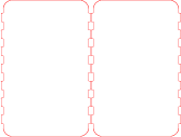
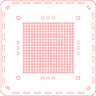 24 24 |  25 25 | 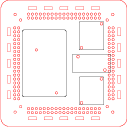 26 26 |
| Top plate | Mid plate | Base plate |
 27 27 | 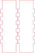 28 28 |  29 29 |
| Front & back | Sides | Heatsink clamp |
 30 30 |  31 31 |  32 32 |
| Diffusers | Diffusers | Shades |
These files along with the Haskell which generated them are included in the github repository.
Control
Having discussed the illumination part of the project, we turn now to the brains. This is a one-off project, so we’d like to use something off-the-shelf and easy to use. Further:
- we have plentiful space and power;
- we need Internet connectivity;
- the software does’t have to do anything complicated or quickly.
Consequently it seemed sensible to use a Raspberry Pi33 running Raspbian34, a Debian derived Linux.
This choice makes the software easier than it would have been on a traditional embedded platform. The development environment is rich with both tools and languages, and there’s enough power floating around to implement everything in, say, Python, without worry.
Further, on Linux there’s already code to talk to lots of devices, reducing the amount of code which needs to be written, debugged, and maintained for this project. Quite apart from the networking stack, I found I could use existing code to handle most of the hardware too.
There are many models of Pi these days. The cool kids would doubtless use a dinky Pi Zero W35, but I had an old Model A36 lying around, so used that instead. This lacks any networking hardware, so I added a cheap USB WiFi dongle.
The Pi needs a 5V supply, which is provided by a cheap Chinese buck converter module from eBay.
PWM
The Pi has hardware support for a PWM output, which you can configure with Devicetree37. However, I used the pigpio38 library which offers up to 31 PWM channels: I used four channels to give each LED its own brightness control.
Occasionally, I’ve seen glitches with the light: a few seconds of flickering. I don’t know if this is a problem with pigpio or my application. Even if there is a problem in the version of pigpio I’m using (v60), it might be fixed in more recent ones.
On the other hand, I always set the channels to the same value, so it would probably be simpler to switch back to a single PWM channel and remove the dependency on pigpio.
The Internet of Things
When building the light, I wanted to connect it to the Internet. I have vague future plans for hooking it into the Apple’s Homekit or Amazon’s Alexa, and it might be fun to try some sort of automation too.
For now though, I just wanted to put the light on the Internet in some way. One approach would be to embed a web-server into the lamp, then provide something like a REST API. However, if I wanted to access the lamp from outside the LAN, I’d have to poke a hole in the firewall, which always seems risky.
AWS IoT
Instead, I embraced the wonder of the Amazon Web Services IoT API39, which:
...enables secure, bi-directional communication between Internet-connected things ... and the AWS cloud over MQTT and HTTP.
There are other similar services, but AWS generally seems to do things well, and I am reasonably confident that Amazon are in this game for the long-term.
AWS IoT allows you to create a device shadow40 in the AWS cloud, which in this case stands as a proxy for the lamp. In particular, the shadow has a brightness attribute, which clients can set. The physical lamp is also an AWS IoT client, and sets the light’s brightness to match the shadow’s brightness.
Rather than just a single brightness level, the device shadow has the notion of a desired level and a reported one. If we want the light to brighter, we change the desired level. When the PWM duty-cycle changes to actually make the light brighter, we update the reported level.
All this works efficiently, in the sense that the lamp doesn’t have to poll to get status: instead the lamp subscribes to the shadow, which then sends updates when the state changes. In practice, I typically see 200 updates a day, but it’s late spring as I write this, so the light gets used most evenings but rarely during the rest of the day.
At an early stage in development, all the updates went via the AWS IoT service, because I was interested to know whether introducing such latency between the knob and the light would be annoying. In practice even though the light is the UK and I’m using the AWS IoT service in North Virginia, the latency is low-enough that it’s this isn’t a problem. The ping time to the AWS server is about 85ms, so perhaps it’s not that surprising. Incidentally light takes about 43ms to travel 8,000 miles in a vacuum.
These days, updates from the knob on the box are handled directly, but the remote controller still sends its commands via AWS even though it seems daft to send signals about 8,000 miles to control a lamp 30cm away.
I should add the system doesn’t work perfectly: there are times when it becomes unresponsive. It has the feel of a connection dying without anyone noticing, at least until a message is sent. I’ve not checked this though, so it’s just a hunch.
Amazon provide a python SDK41 for the MQTT API which was reasonably straightforward to use. Much of the apparent verbosity comes from setting up the connection in a secure way. The SDK is agnostic about how you provide the information: I encapsulated it all in a more opinionated wrapper.
I’m not sure I got the encapsulation quite right: it would be nice to revisit it at some point, and perhaps look at using a generic MQTT library instead. There’s also scope for taking a rather more thoughtful look at the provision of credentials to access the service. For now, I generated these manually, and copied them to the devices. Easy enough, but it doesn’t scale.
Ongoing costs
Although many of the benefits of embracing the IoT are ‘future work’, one downside is clear and present now: Amazon charge for sending messages!
As of now (May 2017), they charge $5 per million messages. At 200 messages per day that’s roughly ¢3 per month. However, as discussed above I think this is unrepresentative, and I suspect the annual bill will be closer to $2.
In practice it is easy to send many more messages during development. I expect this month I’ll clock up charges of perhaps $1, and I’ve not done much work on it. Some apparently innocent ideas can be expensive too. For example, imagine sending a message every second: that’s nearly 3 million per month for which Amazon will charge you about $15. Not a problem for a one-off, but not scalable.
Were I deploying this sort of thing for real, I think more thought would be needed here. For control over the LAN, fast response is clearly useful, but it’s less important if the commands are coming over the Internet from miles away. So it probably makes sense to do LAN control independently of AWS, and only update the device shadow when things have settled.
Input devices
One benefit of using Linux to control the lamp is that the kernel already knows how to talk to various devices. For example, to control the device we have a rotary encoder to set the brightness and a button to toggle it on and off. Code to handle all this is in the kernel: we just need to configure it with some suitable device tree overlays42.
Using kernel device drivers removes all the speed-critical code from our program, which means we can write it in a high-level language. Here, we use python. Explicitly, once enabled devices appear at /dev/input which we can conveniently access with Python’s evdev43 bindings.
Here’s some code which sets up the devices:
import evdev

...

def getDevices():
    devices = {}
    for f in evdev.list_devices():
        d = evdev.InputDevice(f)

        tag  = None
        name = d.name.lower()

        if name  "soc:knob":
            tag = "knob"

        if name  "soc:keypad" or "keyboard" in name:
            tag = "button"

        if tag:
            devices[d.fd] = { "tag":tag, "dev":d }

    return devices
Here’s some which parses the events:
import evdev
from evdev import ecodes

...

r, w, x = select(devices, [], [], idleTime)

for fd in r:
    d = devices[fd]
    for e in d["dev"].read():
      updateState(localState, d["tag"], e)

...

def updateState(s, tag, e):
    brightness = s[brightnessKey]

    # handle rotation events
    if tag == "knob" and e.type  2:
        brightness += e.value * deltaBrightness

    # handle button down events
    if tag == "button" and e.type  1 and e.value  1:

        # e.code tells us which button was pushed

        # custom button toggles state
        if e.code == 256:
            if brightness < maxBrightness * 0.05:
                brightness = maxBrightness
            else:
                brightness = 0

        if e.code == ecodes.KEY_UP:
            brightness += deltaBrightness

        if e.code == ecodes.KEY_DOWN:
            brightness -= deltaBrightness

        if e.code == ecodes.KEY_LEFT:
            brightness = 0

        if e.code == ecodes.KEY_RIGHT:
            brightness = maxBrightness

    brightness = clampTo(0, maxBrightness, brightness)

    s[brightnessKey] = brightness
Another benefit to using the kernel code is that there’s a clean separation between the device driver and application logic. Apart from aesthetic benefits, it means we can test hardware and software independently. For example, the evtest program lets us check that the hardware’s working without writing a test harness.
Temperature sensing
It’s useful to be able to sense the temperature of the LED heatsinks, and again we can do this without writing much software.
First the sensors. Maxim make the DS18S2044, a cheap, widely-available, temperature sensor. It sits on a 1-wire bus, which makes the wiring easy: besides the sensors themselves, we need only a single pull-resistor
Both the 1-wire bus and the DS18S20 are supported by Raspbian, and kind people on the Internet have already documented it45.
Having set this up, measuring the temperature from the command-line is easy:
$ cat /sys/bus/w1/devices/*/w1_slave | fgrep t=
c7 01 4b 46 7f ff 09 10 01 t=28437
d5 01 4b 46 7f ff 0b 10 42 t=29312
c6 01 4b 46 7f ff 0a 10 17 t=28375
da 01 4b 46 7f ff 06 10 31 t=29625
The t= lines show the temperature in milli-Celsius on the four DS18S20 sensors in the lamp: one on each heatsink.
Application code
The application is really rather simple. Essentially we look for changes from either our local controls or the AWS device shadow, decide on a new brightness then push that to both the device shadow and the LED controller.
The only essential complexity is to multiplex changes made locally by the physical controls with other updates to the device shadow.
There’s also some accidental complexity because the input events are handled by a select, but the AWS stuff invokes a callback. In the code below, remoteState gets tweaked at a distance: it might be nicer to put all the AWS stuff in a separate thread which talks to the main code over a socket which we can pass to select. The choices here feel entwined with extending the code to handle Homekit or Alexa, so it will do for now.
while True:
    if bot == None:
        bot = connectToAWS(args.config, remoteState)

    r, w, x = select(devices, [], [], idleTime)

    oldState = localState.copy()
    for fd in r:
        d = devices[fd]
        for e in d["dev"].read():
            updateState(localState, d["tag"], e)

    t = time.time()

    if localState != oldState:
        remote_lockout_expire = t + remote_lockout_period

    if t > update_lockout_expire and sentState != localState:
        awsiot.pushState(bot, localState)
        sentState = localState.copy()
        update_lockout_expire = t + update_lockout_period

    if t > remote_lockout_expire:
        localState.update(remoteState)
        sentState = localState.copy()

    if args.hasLED and localState != oldState:
        setBrightness(gpio, bot, localState)
General Linux configuration
Raspbian is pretty reasonable out-of-the-box. However, besides the hardware specific things above I changed a few system things to suit better an embedded device.
systemd
In the past, to start programs at boot, you would typically write a script in /etc/init.d. Those days are gone now, so for good or ill46 we now write scripts for systemd.
Here’s the script I used for the light:
[Unit]
Description="Toy IOT Light - LED"

[Service]
Type=simple
User=mjo
WorkingDirectory=/home/mjo/aws-iot-toys
ExecStartPre=/usr/bin/sudo /home/mjo/aws-iot-toys/fix-pwm-perms
ExecStart=/usr/bin/python /home/mjo/aws-iot-toys/bin/toy-light-led.py
StandardInput=null
StandardOutput=syslog
StandardError=syslog
Restart=on-failure

[Install]
WantedBy=network-online.target
unattended updates
It’s important that anything on a network gets regular security patches, but it’s a pain to have to login to lots of systems, or even to read mail from them. So I throw caution to the wind, and enable unattended updates47 without configuring mail.
I’m reasonably sure this increases the chances of the light crashing, but reduces the risk of security holes being unpatched, and that’s the right trade-off for me.
syslog
I have one machine which runs an syslog server open to other machines on the LAN. So I configure the lamp to send log messages there:
$ less /etc/rsyslog.d/remote.conf
*.* @@logger.local
It would be nice to send other messages here, e.g. if software isn’t being patched.
Remote controller
 48
48
Having built a light and put it on the Internet, it makes sense to add a remote control. Although it seems odd at first, in retrospect it’s clear that to make a remote control we just clone the lamp code and remove the bit which report setting the new brightness level to the device shadow.
In particular, it’s clear that the remote control has to track the shadow’s state, because it needs to respect any changes made on other devices.
Given that the device is so similar, it makes sense to implement it in a similar way too: a Raspberry Pi plus and rotary encoder.
Code and plans
All of the code for this is on github49 but it’s rather more a brain dump than a nicely formatted repository.
Feel free to contact me if you’re interested.
References
- 1. ../../2018/06/homekit-light.html
- 2. ./yauiotl-case.jpg
- 3. http://www.cree.com
- 4. http://www.cree.com/led-components/products/xlamp-leds
- 5. https://www.digikey.co.uk/products/en?keywords=CXB1304
- 6. https://www.digikey.co.uk/product-detail/en/cree-inc/CXB1304-0000-000C0UB230G/CXB1304-0000-000C0UB230G-ND/5124948
- 7. http://www.molex.com/molex/products/datasheet.jsp?part=active%2F1805550002_SOLID_STATE_LIGHTI.xml&channel=Products&Lang=en-US
- 8. http://www.fischerelektronik.de/en/home-en/
- 9. http://www.fischerelektronik.de/web_fischer/en_GB/heatsinks/B03.1/Heatsinks%20for%20LEDs/$search_result_naviActualPage/1/$search_result_naviLinesPerPage/100/search.xhtml
- 10. http://www.fischerelektronik.de/web_fischer/en_GB/heatsinks/A01/Standard%20extruded%20heatsinks/PR/SK48_/index.xhtml
- 11. ./yauiotl-innards.jpg
- 12. https://www.diodes.com/products/power-management/led-drivers/medium-voltage-dc-dc-led-drivers/part/AL8805
- 13. http://+https://www.sparkfun.com/products/13705
- 14. https://perspex.com/
- 15. https://perspex.com/product-ranges/
- 16. https://perspex.com/product-ranges/perspex-textures/frost/
- 17. http://www.edplastics.co.uk/index.html
- 18. https://perspex.com/product-ranges/perspex-textures/silk-and-satin/
- 19. https://perspex.com/product-ranges/perspex-light/diffuse/
- 20. https://www.rustins.ltd/rustins/
- 21. https://www.haskell.org
- 22. http://projects.haskell.org/diagrams/
- 23. https://en.wikipedia.org/wiki/Saw#Terminology
- 24. ./case-pdfs/out-ply3mm-000.pdf
- 25. ./case-pdfs/out-ply3mm-001.pdf
- 26. ./case-pdfs/out-ply3mm-002.pdf
- 27. ./case-pdfs/out-ply3mm-003.pdf
- 28. ./case-pdfs/out-ply3mm-004.pdf
- 29. ./case-pdfs/out-whiteacrylic-003.pdf
- 30. ./case-pdfs/out-whiteacrylic-000.pdf
- 31. ./case-pdfs/out-whiteacrylic-001.pdf
- 32. ./case-pdfs/out-whiteacrylic-002.pdf
- 33. https://www.raspberrypi.org
- 34. https://www.raspberrypi.org/downloads/raspbian/
- 35. https://www.raspberrypi.org/products/pi-zero-w/
- 36. https://www.raspberrypi.org/products/model-a/
- 37. ../03/rpi-devicetree.html
- 38. http://abyz.co.uk/rpi/pigpio/
- 39. https://aws.amazon.com/documentation/iot/
- 40. http://docs.aws.amazon.com/iot/latest/developerguide/iot-thing-shadows.html
- 41. https://github.com/aws/aws-iot-device-sdk-python
- 42. ../03/rpi-devicetree.html
- 43. https://python-evdev.readthedocs.io/en/latest/
- 44. https://www.maximintegrated.com/en/products/analog/sensors-and-sensor-interface/DS18S20.html
- 45. https://www.modmypi.com/blog/ds18b20-one-wire-digital-temperature-sensor-and-the-raspberry-pi
- 46. https://en.wikipedia.org/wiki/Systemd#Criticism
- 47. https://wiki.debian.org/UnattendedUpgrades
- 48. ./yauiotl-remote.jpg
- 49. https://github.com/mjoldfield/yauiotl
![[ Atom Feed ]](../../atom.png "Atom Feed")