

Introduction
The Ikea Jansjö work lamp is a simple, cheap (~£10) LED light. It comes in desktop1, and clamp2 variants, and you even have (some) choice of colour!
I’ve got a bunch of them around the house, but don’t take my word for it: Ben Krasnow likes them too3!
The only problem with them, is that sometimes they’re too bright, so I thought I’d make a dimmer for them.

Details
From what I can tell, both desk and clamp lights have a simple LED in the lamp body, a switch in the cable, and a wall-wart with some sort of current control.
The supply for my desk lamps claim an output of 4V, whereas the clamp supply boasts a more generous 7V. This might reflect different vintages of lights, or just different batches.
PWM for the win
Given that there are different designs in the wild, I thought the most robust way to control the brightness was to just modulate the LED’s output with a relatively slow pulse-train, and vary its duty cycle.
Switching the power with MOSFET is an obvious choice, and after consulting The Art of Electronics4 a simple 5555-based oscillator seemed a sensible way to drive it.
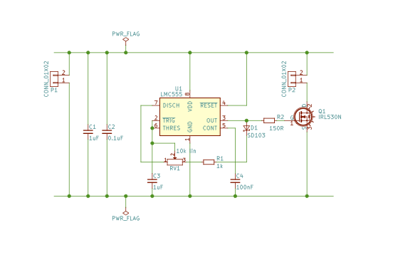
The classic 555 oscillator circuit needs a little fettling to produce duty-cycles less than 50%. I just copied the book to give this schematic:
 6
6
Component details
The circuit is trivial, but there are a few points to note:
- The classic 555 needs a supply voltage of at least 4.5V, which won’t do. So, I used a cheap CMOS version too: the LMC5557.
- The IRF5308 MOSFET is complete overkill: it can switch up to 12A, but it seemed to me that this board might be more generally useful to warrant some headroom. 4V is just enough to saturate the device.
- The potentiometer is a linear slide potentiometer from Bourns’ PTA series9. The fixed series resistor sets a lower-bound on the duty-cycle i.e. a minimum brightness for the light.
- Although not shown here, there’s also a power switch in the main power rail. Small rocker switches seemed hard to find, I used a CWT12AAS110 from NKK.
Performance
The circuit should oscillate at
\[ f_{OSC} = \frac{1.44}{R C}, \]and here, \(R = 11\textrm{k}Ω\) and \(C = 1μ\textrm{F}\). So we expect \(f_ ≈ 130\textrm{Hz}\).
Characterization
I did most of my testing with a 7V light. Without the dimmer in place, the power-supply generates 6.90V which dropped to 6.89V when the LED was connected. The LED drew a suspiciously round 200mA of current.
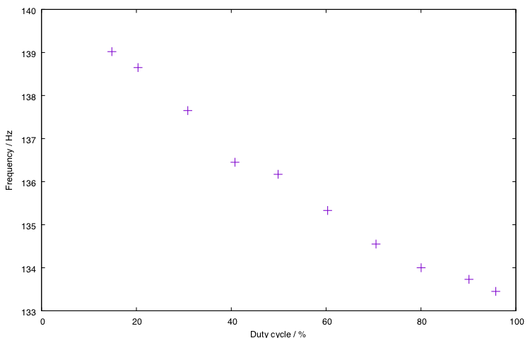
The circuit’s description in The Art of Electronics talks about being able to change the duty-cycle over almost the whole-range and without affecting the frequency much, so I thought I’d measure this.
 11
11
The end points on this plot correspond to the extreme positions of the plot. You can see that the duty-cycle ranges from about 15% to 95%: the asymmetry comes from fixed resistor which provides a lower bound on the duty-cycle. It has a value of about 10% of the pot, so the basic performance of the circuit is roughly 5% to 95%.
At a duty-cycle of about 50%, the frequency is about 136Hz: about 5% high. That seems well within the expected tolerance of the capacitor a X7R 0603 ceramic.
We also see about a 5% change in frequency as the duty-cycle changes: high duty-cycle corresponds to low frequency and vice versa.
Redoing the experiment at a different time of day gave frequencies about 1.5Hz lower than shown above: I think this is probably a temperature effect.
High-frequency structure
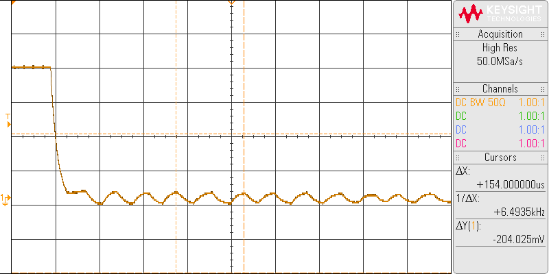
The figure below shows the current flowing to the LED at a duty-cycle of about 63%, measured using a µCurrent12.
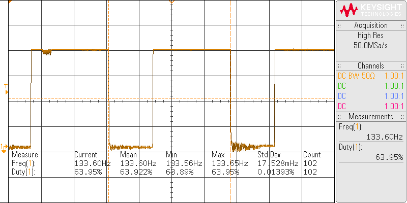
If we zoom-in on the region where the MOSFET is on, we can see regular spikes, which presumably come from a switching regulator in the wall-wart. In the trace shown they are spaced 25.4μs apart, which corresponds to a frequency of 39.4kHz. This isn’t constant though: at other times I've seen significantly lower frequencies.
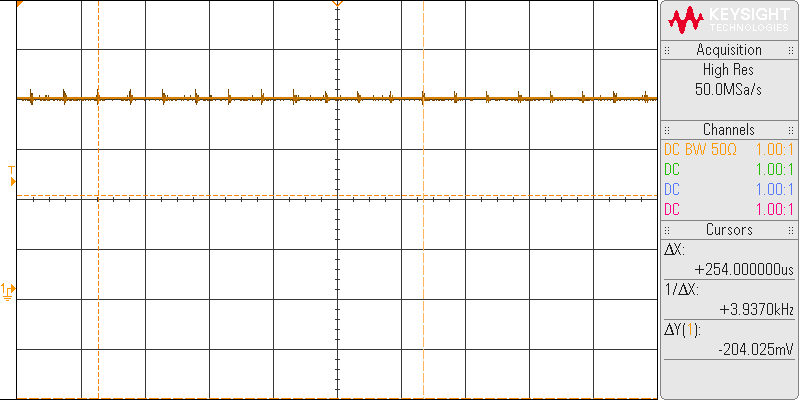
There is also some oscillation in when the MOSFET is off. I’m not sure where this comes from, nor whether it’s just a measurement artefact or a real issue. The frequency is odd: about 13kHz.
The effect of voltage
I measured the performance of a couple of 4V lamps non-invasively with a photo-diode:
| Lamp | Dim | Bright | ||
|---|---|---|---|---|
| f / Hz | duty-cycle | f / Hz | duty-cycle | |
| 7V | 137.9 | 14.1% | 133.1 | 95.5% |
| 4V #1 | 128.3 | 15.8% | 118.7 | 95.4% |
| 4V #2 | 131.9 | 16.7% | 123.0 | 95.8% |
Summary
It is easy to point to ways in which the circuit is not a perfect fixed-frequency oscillator with a duty-cycle adjustable between 0 and 100%. The imperfections are slightly more marked at 4V than 7V, presumably because at least some of them come from the forward voltage of the diode, which becomes more significant as the voltage falls.
Although three samples isn’t enough to draw serious conclusions, the oscillator appears to run faster at higher voltages. I wonder if this comes from the voltage dependence of the capacitance13 of the MLCC timing capacitor.
Taking a step back though, these issues are minor. The circuit works as a perfectly good PWM controller.
Design files
 14
14
Schematic and PCB
The electronics were designed in KiCad and you can download the files from GitHub15.
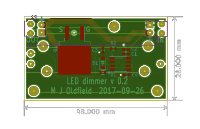
The PCB is a somewhat generous 48mm long and 28mm wide: the former’s governed by the length of the pot., and the latter by the desire to mount the pot centrally whilst allowing space for board connectors.
With the exception of the pot and connectors, construction is surface mount, with 0603 passives.
Enclosure and front panel
 16
16
The PCB fits neatly into a Camden Boss RX2KL0717 potting box. I replaced the lid with 3mm laser-cut acrylic, and a PDF for the cuts is also in the repo.
Although the PCB has mounting holes, in practice the whole assembly is fixed to the front panel via the mounting holes on the potentiometer.
Somewhat idiosyncratically, the PDF for the laser cutter is produced by a Haskell18 program.
Installation
This was relatively easy: I cut out the existing switch and replaced it with the dimmer module.
Somewhat annoyingly the strain-relief holes in the PCB were a bit too small and so couldn't be used.
References
- 1. http://www.ikea.com/gb/en/products/lighting/work-lamps/jansjö-led-work-lamp-black-art-00169659/
- 2. http://www.ikea.com/gb/en/products/lighting/work-lamps/jansjö-led-wall-clamp-spotlight-white-art-00315651/
- 3. https://youtu.be/YBQp04glQqc?t=4m8s
- 4. https://artofelectronics.net
- 5. https://en.wikipedia.org/wiki/555_timer_IC
- 6. ./dimmer-schematic.pdf
- 7. http://www.ti.com/product/LMC555
- 8. https://www.infineon.com/dgdl/irf530nspbf.pdf?fileId=5546d462533600a4015355e38eb4199c
- 9. http://www.bourns.com/products/potentiometers/slide-potentiometers/product/PTA
- 10. http://www.nkkswitches.com/wp-content/themes/impress-blank/search/inc/part.php?part_no=CWT12AAS1
- 11. ./phi-f.pdf
- 12. http://www.eevblog.com/projects/ucurrent/
- 13. https://en.wikipedia.org/wiki/Ceramic_capacitor#Voltage_dependence_of_capacitance
- 14. ./dimmer-pcb.pdf
- 15. https://github.com/mjoldfield/jansjo-dimmer
- 16. ./dimmer-panel.pdf
- 17. http://camdenboss.com/enclosures/potting-boxes/potting-boxes-with-lid-hb
- 18. https://www.haskell.org
![[ Atom Feed ]](../../atom.png "Atom Feed")